AIoT Intelligent IoT Professional Solution
Multi scenario high reliability localization solution, empowering efficient upgrading of intelligent IoT


OPTOLEK Bluetooth module solution based on Nordic chip
Anti interference, strong penetration, long-distance transmission, helping to upgrade the intelligence of medical equipment
From security cameras, smart homes, to smart cockpits
AI automatic tracking, motion camera
Multi protocol compatible wireless RF and high-throughput storage
For intelligent consumption, wearability, edge computing and AIoT devices


2025-11-14

Introduction
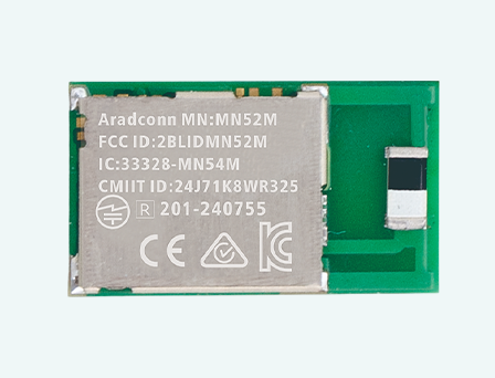
This report is dedicated to the in-depth performance validation of Aired Technology's newly released MN54L BLE Bluetooth Module, which incorporates the Nordic next-generation nRF54L Series IC. The core objective of this testing is to measure the maximum effective bidirectional communication range (MASTER/CENTRAL to SLAVE/PERIPHERAL) in an open field, benchmarked against industry-standard module-to-module measurement protocols.
In our prior communication tests involving the MN52H and MN54L Series modules, we simulated common consumer scenarios, such as communication between the BLE module and a smartphone (e.g., iPhone). While those tests successfully verified product performance in real-world consumer applications, the results were fundamentally limited by the low transmit power (TX power) of the consumer devices. Consequently, those tests could not showcase the absolute Radio Frequency (RF) performance limit of the modules themselves.
(Refer to the previous iPhone connection test report)
Given these constraints, the design goal for this MN54L test is to directly inherit the high-standard validation methodology established by the MN52H testing. This ensures the data accurately reflects the most robust performance achievable by the MN54L module in complex and demanding applications, such as Bluetooth Mesh, Thread, and Matter. For consistency with previous tests, we utilize the MN52H-U40 as the MASTER/CENTRAL device, communicating bidirectionally with various antenna configurations of the MN54L modules. Testing was conducted in an open environment, specifically a beach location, to minimize interference from geographical obstacles and surrounding radio signals, thereby providing the most accurate and valuable reference data on the module’s ultimate wireless transmission performance.
1. Test Objectives
· Validate the effective communication range of the MN54L BLE module's bi-directional communication (MASTER/CENTRAL TO SLAVE/PERIPHERAL) in an open field environment.
· Compare the communication performance of different antenna types (CHIP / PCB / u.FL).
2. Test Date
✅ November 07th, 2025
3. Test Environments
✅ Outdoor Environment: Open and unobstructed area.
4. Equipment Required
✅SLAVE/PERIPHERAL Device (Emitting Board):
l Test Modules (MN54L-C15, MN54L-P15, MN54L-U15)
✅MASTER/CENTRAL Device:
l Test Equipment (MN52H-U40)
✅Test Software: Arad Technology Test Firmware for Bluetooth Module.
✅Distance Measurement and Recording Tools: Google Map, Mobile GPS Positioning.
5. Test Parameters
Parameter | Description |
TX Power | +8 dBm |
PHY Mode | 125K (Long Range); 1M |
Packet Size | 20 bytes |
Direction | Line-of-sight (LOS) |
Antenna Height | 3 meters above ground |
Transmission Mode | Connection mode (Effective Packet Transmission) |
Environmental Conditions | Temperature: 31°C, Humidity: 78% |
6. Test Procedure
This procedure aims to measure the maximum transmission range of the MN52H Bluetooth module under various antenna configurations in standardized and repeatable conditions.
6.1 Test Preparation and Connection Establishment
1. Equipment Settings and Transmission Parameters:
l Ensure both the SLAVE/PERIPHERAL devices (MN54L-C15, MN54L-P15, MN54L-U15) and the MASTER/CENTRAL device (MN52H-U40) have their TX Power set to +8 dBm.
l Transmission Rate Confirmation: Set the 125K mode to transmit 1 packet per second (PPS); set the 1M mode to transmit 4 packets per second (PPS).
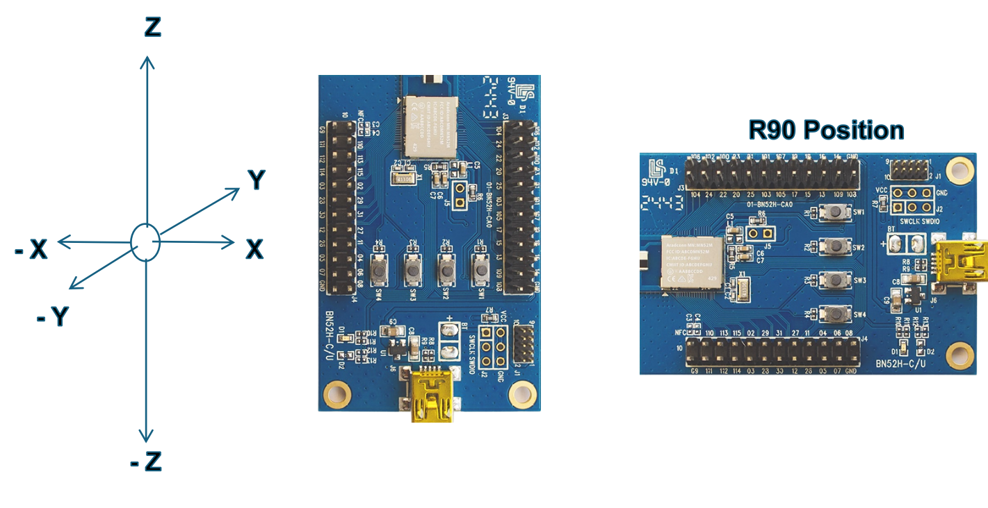
2. Starting Point Positioning: Fix the SLAVE device at the starting point, with the antenna 3 meters above ground level, ensuring all antenna directions face the planned movement path.
3. Connection Confirmation: The MASTER device establishes an effective connection with the SLAVE device at the starting point and performs bi-directional packet transmission. The packet reception status will be displayed and confirmed by the flashing LED on the module.
6.2 Distance Measurement and Data Recording
1. Incremental Testing: The MASTER device moves outwards along the Line-of-sight path in increments of 50 meters.
2. Halt and Monitoring: At each measured distance point, confirm the connection status of the MASTER device and continue moving outwards.
l Connection Quality Confirmation: Judge the connection status by observing the flashing LED. A solid off or irregularly flashing LED indicates packet loss.
l Continuous packet transmission and reception are defined as an effective connection.
3. Angle Influence Test: At the distance where the signal begins to attenuate, test the effect of different rotation angles of the SLAVE device antenna on the Packet Success Rate (PSR) to determine the signal radiation pattern and polarization effects of different antenna types.
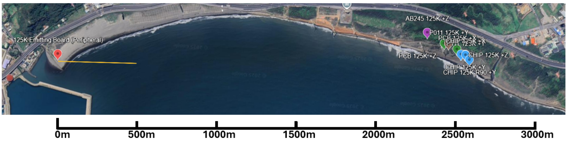
4. Maximum Range Determination: Continue moving until the connection cannot be stably maintained (e.g., continuously low Packet Success Rate or complete connection interruption, at which point the LED will stop flashing). Use Google Map and GPS positioning tools to accurately record the disconnection distance and the environmental characteristics at the point of disconnection.
7. Test Results Summary
l Comparison of maximum range under different transmission orientations.
l Performance comparison table for each antenna model.
l Test device version and firmware information.
l Record of test anomalies (e.g., packet loss).

1M mode

125K mode
8. Test Conclusions and Observations
The validation results for the MN54L module demonstrate a significant leap in long-range transmission performance, building upon the excellent foundation established by the MN52H.In our previous testing of the MN52H module (across both 125K and 250K PHY modes), the maximum stable transmission distance was highly consistent, consistently falling between 2.2 km and 2.3 km. Crucially, the signal discontinuity points were invariably located near several large wind turbines within the test environment. These massive structures were identified as the primary physical obstructions, preventing the testing from achieving true Line-of-Sight (LOS) measurement conditions and leading us to conclude that the measured range did not represent the MN52H module's absolute RF performance limit. The most significant difference observed in the MN54L module validation is the marked enhancement in its transmission capability compared to the MN52H, successfully overcoming the geographical constraint posed by the large wind turbines. The MN54L maintained an active and effective signal connection at the exact location where the MN52H previously experienced link discontinuity. This strongly proves the MN54L’s ability to effectively handle real-world environmental challenges, enabling longer and more reliable bidirectional communication for demanding industrial and infrastructure applications.
 、
、
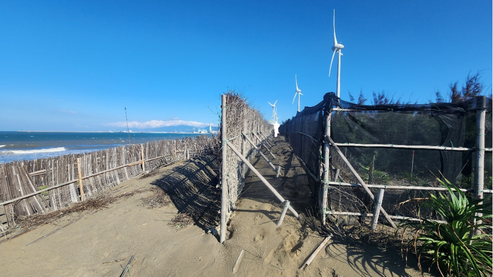

Image and Text Copyright Statement:
All text and image content in this article (including but not limited to headings, body text, analysis, and summaries) are the copyright of Arad Connectivity Co., Ltd. Any form of reproduction, reprinting, modification, or commercial use without written authorization is strictly prohibited.
Get Ready for Our Latest Episode of BLE Tech Pulse Decoded on Aradtube!
We're diving deeper into this fascinating topic! Subscribe to our channel and hit that notification bell so you don't miss our latest video releases.
YouTube: https://www.youtube.com/@Aradconn
bilibili: https://space.bilibili.com/3546930479106305/upload/video
★ Source: Arad Connectivity Co., Ltd. / The content of this article has obtained the authorization for promotion, release and reprint from Arad Connectivity Co.,Ltd.
For more information on Bluetooth wireless modules and other product solutions, please visit our website or contact us by email.
You can leave your contact information, and we will get in touch with you as soon as possible

Scan WeChat
Copyright © Dongguan Optolek Technology Co., Ltd. All Rights Reserved. WEB
Call Us
Scan WeChat