AIoT Intelligent IoT Professional Solution
Multi scenario high reliability localization solution, empowering efficient upgrading of intelligent IoT


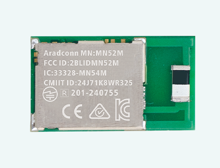
OPTOLEK Bluetooth module solution based on Nordic chip
Anti interference, strong penetration, long-distance transmission, helping to upgrade the intelligence of medical equipment
From security cameras, smart homes, to smart cockpits
AI automatic tracking, motion camera
Multi protocol compatible wireless RF and high-throughput storage
For intelligent consumption, wearability, edge computing and AIoT devices





2026-08-13

Introduction
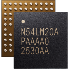
Compared to the MN54L-15 series modules (9.3x14.5x2.1mm), the MN54LM-20A modules feature a more compact size (7.5x13x2.0mm), with the MN54LM-S20A module being the smallest at (7.5x10.2x2mm). This test aims to explore "what is the impact of size reduction on the effective connection range of the modules?", thoroughly verify the maximum effective communication range of the Arad Connectivity MN54LM-20A series BLE modules when communicating with an iPhone 7 smartphone under 1M PHY, and evaluate the communication performance across all axes for modules equipped with built-in CHIP, PCB antennas, and external u.FL antenna versions.
1. Test Objectives
To completely verify the maximum effective communication range of the MN54LM-20A BLE series modules when communicating with an iPhone 7 smartphone under 1M PHY
To test the communication performance of built-in CHIP, PCB antennas, and external u.FL antenna version modules across all axes with the smartphone.
2. Test Date & Environment
Test Date: July 28, 2026
Test Environment: Outdoor environment, Mazutian Riverside Park, New Taipei City
3. Equipment Required
SLAVE/PERIPHERAL: MN54LM-C20A, MN54LM-P20A Modules, MN54LM-U20A, MN54LM-S20A Modules
MASTER/CENTRAL 1: iPhone 7 Tx Power: 0 dBm
External Antenna Types
ANTX100ETHAB24553
ANTX100P011B24003_1
ANTX100P111B24003_0
Test Software: LightBlue®; Aradconn custom BLE firmware.
Measurement Tools: Google Maps, Mobile GPS Positioning.
4. Test Parameters
TX Power: +8 dBm (Set on MN54LM-20A series modules); +0 dBm (iPhone 7)
PHY Mode: 1M (Standard BLE)
Packet Size: 20 bytes; 4 packets per second
Direction: Line-of-Sight (LOS) path maintained for distance measurement.
Antenna Height: 3 meters above ground level
Transmission Mode: Connected mode (Verifying valid packet transmission, receiving at least one packet set).
Environmental Temperature: 33°C, Humidity: 71%.
5. Test Procedure - iPhone 7 (MASTER, 0 dBm)
5.1 Preparation and Connection Establishment
1. Equipment Setup: Establish an active connection between the iPhone 7 and SLAVE devices (MN54LM-C20A, MN54LM-P20A, MN54LM-U20A, MN54LM-S20A), and verify packet reception.
2. Transmission Rate: Set to 1M mode, transmitting 4 packets per second.
3. Starting Point Positioning: Fix the SLAVE device at the starting point, 3 meters above the ground, ensuring all antenna directions face the intended movement path.
4. Connection Check: Observe the LightBlue® screen to confirm connection status.
5.2 Distance Measurement and Data Logging
1. Incremental Test: The MASTER device (iPhone 7) moves outward along the line-of-sight distance path in 10-meter increments. Stop and Monitor: At each measurement point, check connection quality via the LightBlue® screen.
2. Limit Distance Determination: Continue moving until the connection can no longer be stably maintained (e.g., success rate remains persistently low or LightBlue® connection completely drops, at which point indicator lights stop flashing).
3. Use Google Maps and GPS tools to precisely record the disconnection distance and environmental characteristics at the time of disconnection.
6. Test Records (Maximum Effective Connection Distance)
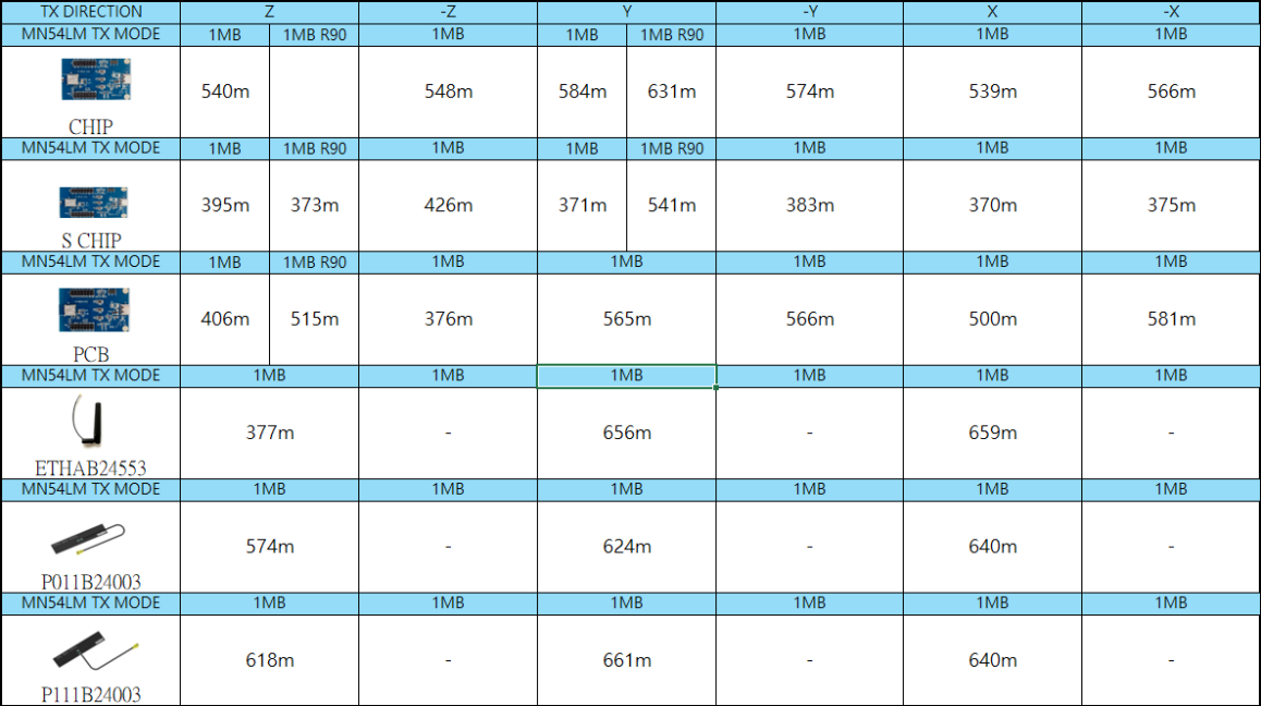
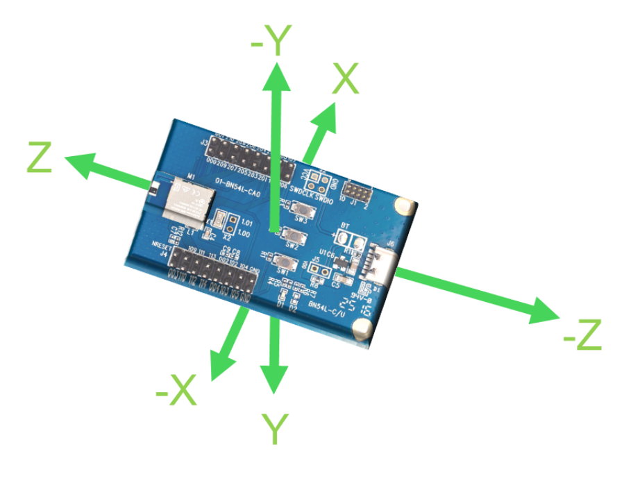
The table below shows the maximum effective distance at which the MN54LM-20A series modules maintained a stable bidirectional connection and received at least one packet over long ranges:
Test Conclusions
Synthesizing the field test data from open-field conditions, as the MN54LM-20A series modules feature reduced physical dimensions (especially the ultra-compact MN54LM-S20A), their overall wireless transmission distances are indeed impacted to varying degrees. However, through cross-validation across all axes and rotation angles, several key conclusions can be drawn:
1. Trade-off Between Size and Performance: The reduction in physical volume directly impacts the radiation efficiency of the built-in antennas. The miniaturized S CHIP (MN54LM-S20A) sees its communication range drop to the 370–541 meter range across axes, whereas standard-size CHIP and PCB variants maintain ranges between 400 and 660 meters.
2. Antenna Directivity and Rotational Optimization: Physical placement and rotation angles (such as R90°) significantly impact the transmission distance for specific antennas (like CHIP and PCB antennas). Proper rotation and directional alignment (e.g., CHIP antenna reaching 631–667 meters after Y-axis rotation) can effectively overcome directional performance constraints.
3. Advantages of External Antennas: For space-constrained applications requiring maximum transmission range, pairing with external u.FL antennas (such as P111B24003) significantly boosts performance, achieving stable connections up to 661 meters along specific axes—serving as an alternative solution to counteract range degradation caused by module miniaturization.
Image and Text Copyright Statement:
All text and image content in this article (including but not limited to headings, body text, analysis, and summaries) are the copyright of Arad Connectivity Co., Ltd. Any form of reproduction, reprinting, modification, or commercial use without written authorization is strictly prohibited.
★ Source: Arad Connectivity Co., Ltd. / The content of this article has obtained the authorization for promotion, release and reprint from Arad Connectivity Co.,Ltd.
For more information on Bluetooth wireless modules and other product solutions, please visit our website or contact us by email.
You can leave your contact information, and we will get in touch with you as soon as possible

Scan WeChat
Copyright © Dongguan Optolek Technology Co., Ltd. All Rights Reserved. WEB
Call Us
Scan WeChat